General Device Info
General device information section covers basic device and interface information.
-
Type
- Type is selectable (I2C, SPI, UART). Once you have selected the specific bus type e.g. related bus options will be available for selection and this type will be used for a driver generation.
- Role
-
Bus options
-
I2C
- Frequency
- Address value
- Address size
-
SPI
- Supported modes
- MSB first
- Ship select active low
- Full Duplex
- Max frequency
- Data size
-
I2C
Registers
The registers section is a register map of the device where user can manually add new register and change the extracted register list. The number at the top of the chapter heading indicates the amount of extracted and manually created registers of this component. Default view of the register map is a list of:- Name
- Address
- Size

Detailed Register Info
User can expand any register to get access to detailed register information:- Type
- Access
- Default value
- Description
- Data Type

Manually Adding a Register
To manually add a register, click on the ”+ New Register” to manually add the missing register:
Data Types
This section describes the Data Type section of the device model and possible interactions with data types. Extracted data types are presented as a list of data types.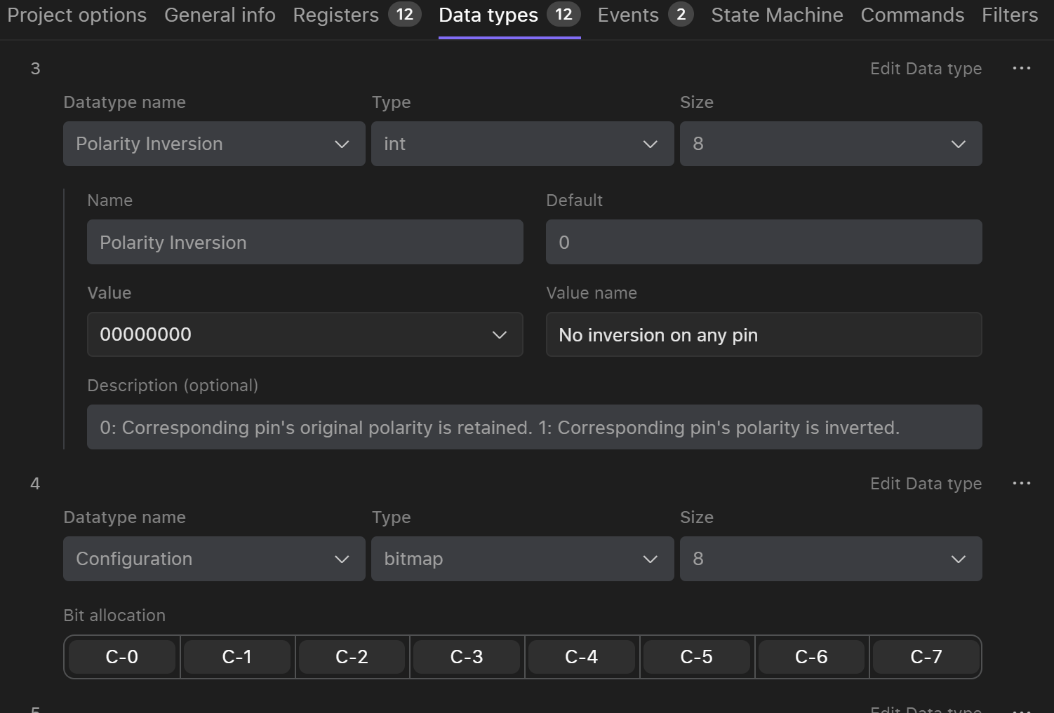
- Name
- Type
- Size
- Default value
- Values
- Value name
- Description
- UINT
- Bitmap
-
Change bitmap size: 8, 16, 24, 32, 40
- To change the size of the bitmap user has to select the corresponding size in the size dropdown.
-

-
Add missing offsets
- To add new offset user have to click on the + in a bitmap and fill the required information for the offset.
-

-
Manually change offset size
- In order to change the size of the offset user has to manually drag the offset by the border to increase the size. User can drag the offset forward, backward and down.
-

- Add values for offsets
Error Handling
AI data extraction can contain mistakes that could be identinfied by algorithms. If any of the data types has a potential error or mistake it will be spoted in Erros and Warnings navigation bar in the header of the screen.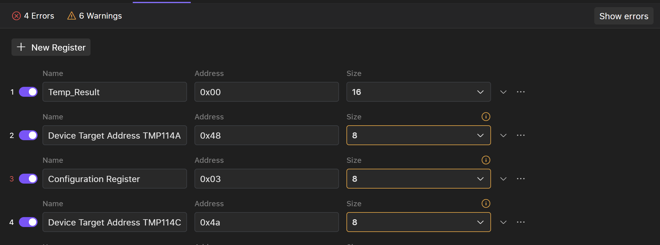
-
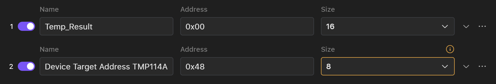
Inconsistency in datatype size
- Some sizes of the data types may be different from the rest of the data type and may require user attention.
-
-
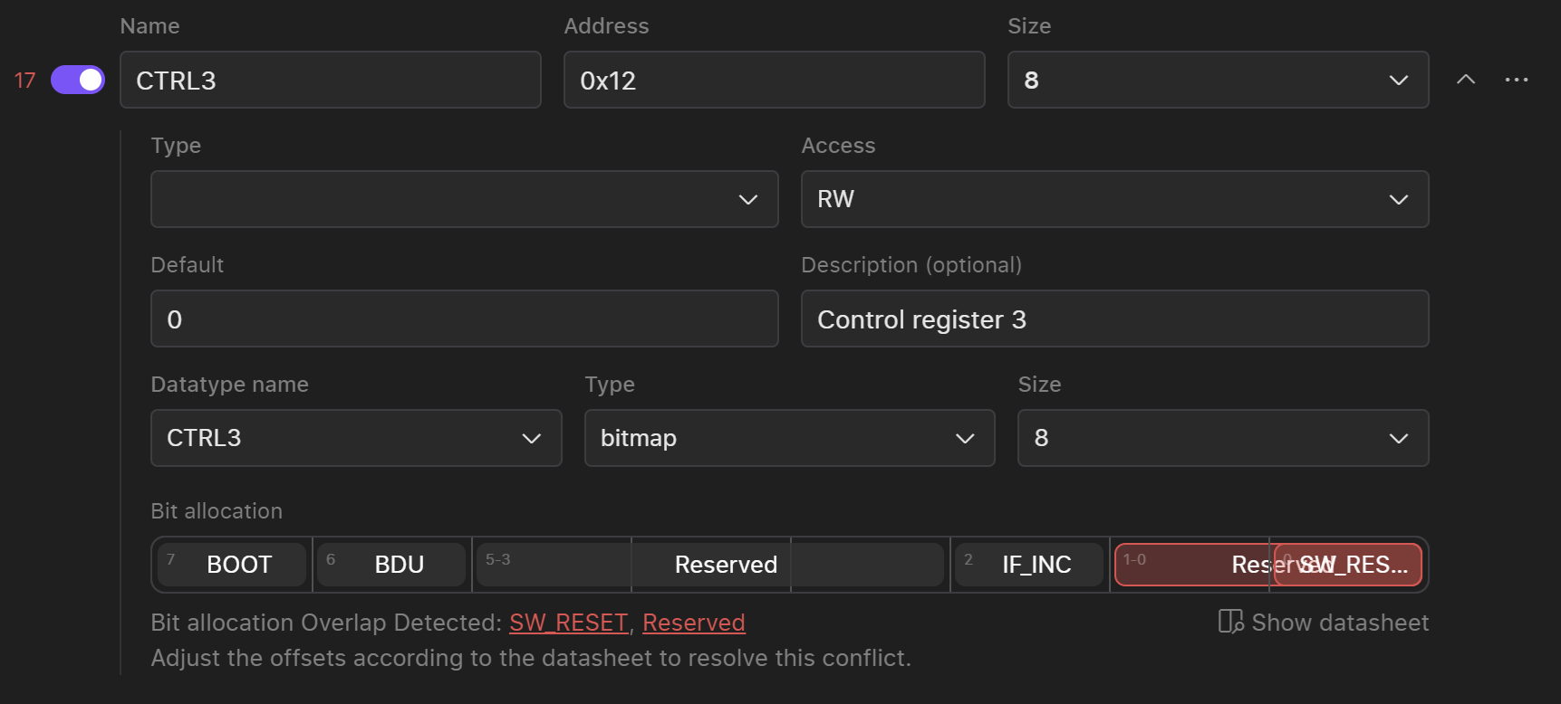
Overlapping of the offsets
- Some extracted offsets may have the same number so user need to delete incorrectly overlapping offsets or manually rearrange it. To check the bit aalocation on the datasheet
-
-
Number of offsets exceeds the size of the data type
-
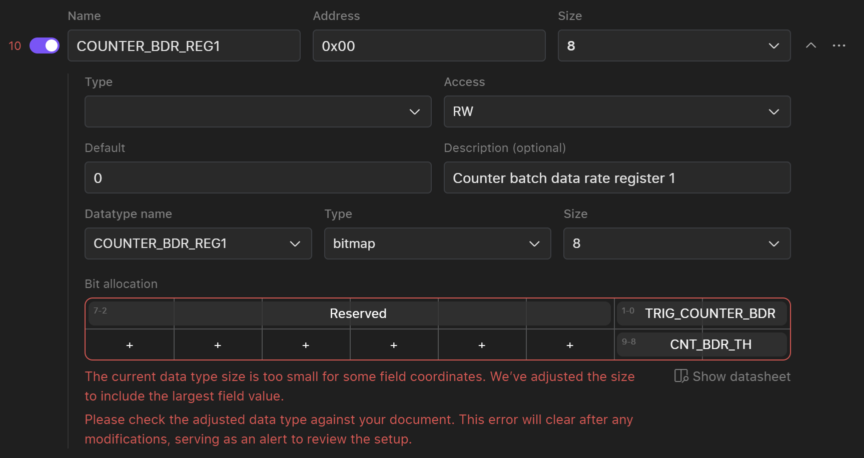
- Some of the offset number may be higher then the size of the data type. To solve this issue user have to increase the size of the data type manually and in case of wrong extraction delete the offset.
-
Events
In this section users can see all of the events/interrupts that are presented in datasheet.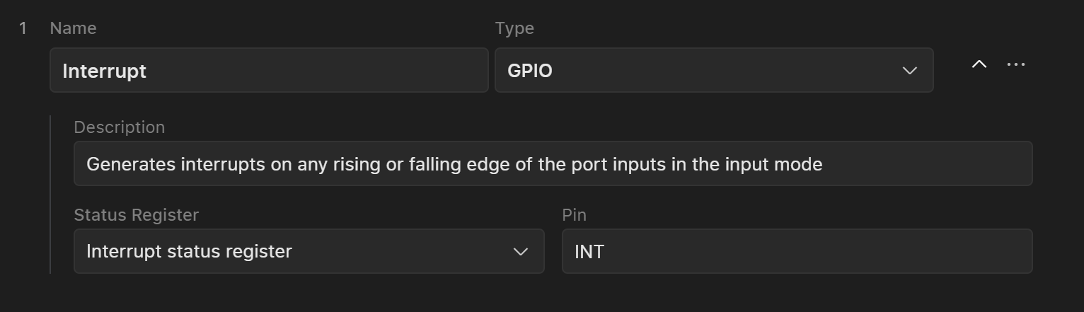
- GPIO
- MSG
- Timer
- GPIO: PIN, Status Register
- Timer: Interval
-
MSG: Length, Preambula:
{type(raw, string), value}
Setup Section
In the Setup section, you can configure initial values that will be written to the registers during device initialization.1. Adding Registers to the List
To add registers to the list:
-
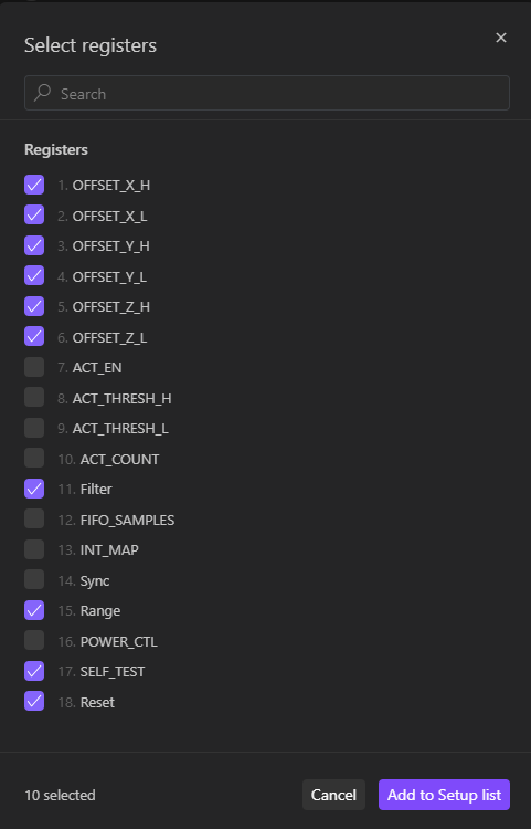
Open the Register Selection Interface:
- Click on “Add Registers” located in the middle or at the top of the tab.
-
Select Registers:Note: Only registers with
W(write) andRW(read/write) access types will be displayed. If some registers are missing, return to the Registers section to update their access types.-
Choose the registers you want to set initial values for from the list.
-
Choose the registers you want to set initial values for from the list.
-
Multiple Selections:
- You can select any register multiple times if needed.
2. Arranging Register Order
Once all registers are selected: Rearrange Registers:- Drag the registers to the desired positions within the list to adjust their order.

3. Setting Register Values
Choose one of these methods to set values for each register:
-
Enter Decimal or Hex Value:
- Input the desired value directly. Use the top page selector to choose between Decimal (DEC) or Hexadecimal (HEX) format.
-
Adjust Bits Using the Bit Table:
- Click on individual bits in the bit table to toggle their values between 0 and 1.
-
Select Values from the Value Breakdown Table:
- Choose values for each field from the value breakdown table.
Finalizing Setup
Once you have added, arranged, and configured the registers with their values, review your settings to ensure accuracy. These configurations will be applied during device initialization, so verify that all entries are correct. For additional verification, you can use the PDF backlink mode to cross-check your setup against the provided documentation. This ensures that all configurations align with your requirements before finalizing the setup.PDF Mode
Along with any chapter of the device model user can turn on a PDF mode and corresponding PDF datasheet will appear in the same screen along with digital component model.
